Allsky Projections Rendering on GPU (using Ray-tracing)
Hi folks,
This is my first article. I wanted to write something about non-linear (allsky) projection rendering using WebGPU (or your favorite rasterizer).
What are Allsky Projections ?
The classical “perspective” projection is by far the most commonly used type of projection in computer graphics (games, movies, computer vision, …). It is nowadays defined in a lot of linear algebra libraries. This projection imitates what a camera or the eyes are doing. We will not talk about this one in this article.
What I want to talk with you about is: allsky projections rendering.
So what is this beast ?
Looking at a sphere with your eyes, you should be able to see only the half of it, the other half remaining unknown. On the opposite, there are projections, i.e. the mercator projection, that can project the whole sphere onto your 2D screen, allowing you to see it entirely! This is why these projections are said “allsky”: with just a look, you see the full surface of the sphere, every longitudes and latitudes of it.
These projections are very useful to visualize revolutionary objects such as spheres, cones or cylinders. They are used in astronomy to represent the sky from the earth point of view (i.e. a sphere).
Many allsky projections exist, each having their own properties. The most of them have been designed for a specific scientific use case. If you are curious about map projections, wikipedia has a page where you will find a plenty of very strange ones!
Rendering a Textured Sphere
Mapping a texture on a sphere is not so simple. You will always find some distortions either around the poles or near the equator. This is an active research subject. A lot of mathematical tesselations of the sphere have been defined.
In astronomy, we are using the HEALPix tesselation. HEALPix stands for: Hierarchical Equal Area isoLatitude Pixelisation. HEALPix has, like many sphere tesselation, pros and cons. Before explaining what they are. Let me explain what this tesselation consists of.
The HEALPix tesselation is perfectly hierarchical. At level 0, the sphere is divided in 12 equal area base cells. At level one, each of the 12 base cells are divided into 4 new ones which are also equal-area sized. This leads to 48 cells at level 1.
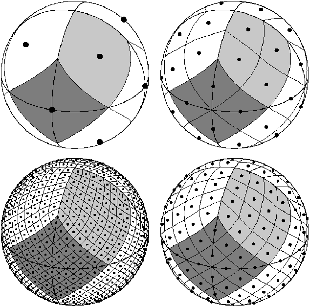
More generally, for a given level $N$, the number of equal area cells is $N_{pix} = 12 \times 4^N$
One difficulty of the HEALPix tesselation is that the cell frontiers are not great arcs, i.e. they cannot be contained in a plane passing by the center of the sphere. Therefore HEALPix is not straightforward to implement. Another problem is that cells around the pole are quite distorted as you can see in the image above. You will also find some cells that do have only 7 neighbors instead of 8.
To conclude, the HEALPix has interesting features:
- It is hierarchical. A parent cell divides into four children. They are fully contained in the parent and the union of them gives the parent cell. Some tesselation does not satisfy this property.
- For a given level, all the cells have the same area.
These two features combined makes HEALPix very interesting for storing image tiles. Aladin and its web app counterpart called Aladin Lite are satellite image viewers. They use equal sized ($512 \times 512$) tile images mapped to HEALPix cells for each level $N \in \mathcal{N}$. When the user is zooming and moving, the tile images corresponding to the HEALPix cells inside the screen are downloaded and rendered.
Why does the Traditional Rendering Approach leads to Issues ?
The standard way of rendering a sphere would be to project the vertices of each triangles (two per HEALPix cells).
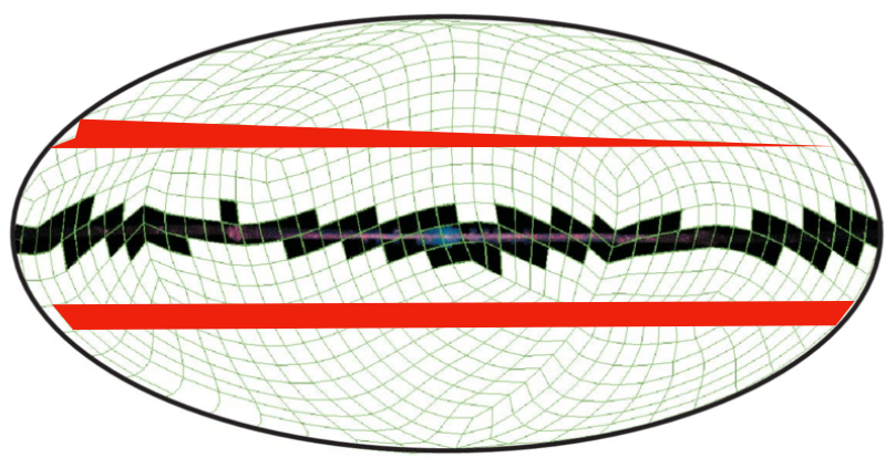
This can be done in the vertex shader for example. If we do that, once projected, the triangles located at the border of the view will cross the whole screen. We will end up with one vertex in the left of the screen while the two other will remain in the right side of the screen.
This is something that can be handled (with difficulty but it can). Here is how:
At each frame we need to discard the triangles crossing the projection. You can spot the triangles by looking if the projected vertices are given in the opposite direction of the other triangle vertices (in the counterclockwise order instead of clockwise).
Maybe this can be done in a specific step of the rendering pipeline. Or you can simply do it on the CPU side and update the vertex buffer at each frame:
- I did not investigate the first solution but it may use some recent shader programming features. This can be problematic if you want to make things cross compatible with old computers or for the web (using WebGL for example).
- The latter one is CPU intensive. It requires to do the projection of all the triangles on the CPU side in order to discard the rendering of some of them. And we need to do that whenever the user moves…
While this may be handled, you will not have perfect projection borders as some triangles will be discarded…
We need to consider another approach…
Considering the Problem the Other Way
How to solve the problem then ?
A better approach is to consider the problem in the opposite way. Instead of defining your 3D vertices and projecting them to your screen, why not define the 2D footprint of your projection and “un"project the 2D screen pixels to get their 3D corresponding coordinates?
You can:
- Unproject your 2D screen triangle vertices in the VS (Vertex Shader)
- Give the resulting 3D vertices to the FS (Fragment Shader). Then in your FS, each fragment will have an interpolated 3D coord computed from the 3 vertices of the triangle containing it.
This approach will result in distortions especially within big and thin long triangles. At the border, the derivatives of the projections in each directions are usually big. This results to distortions when using linear interpolation.
Precompute the Position for each Pixel
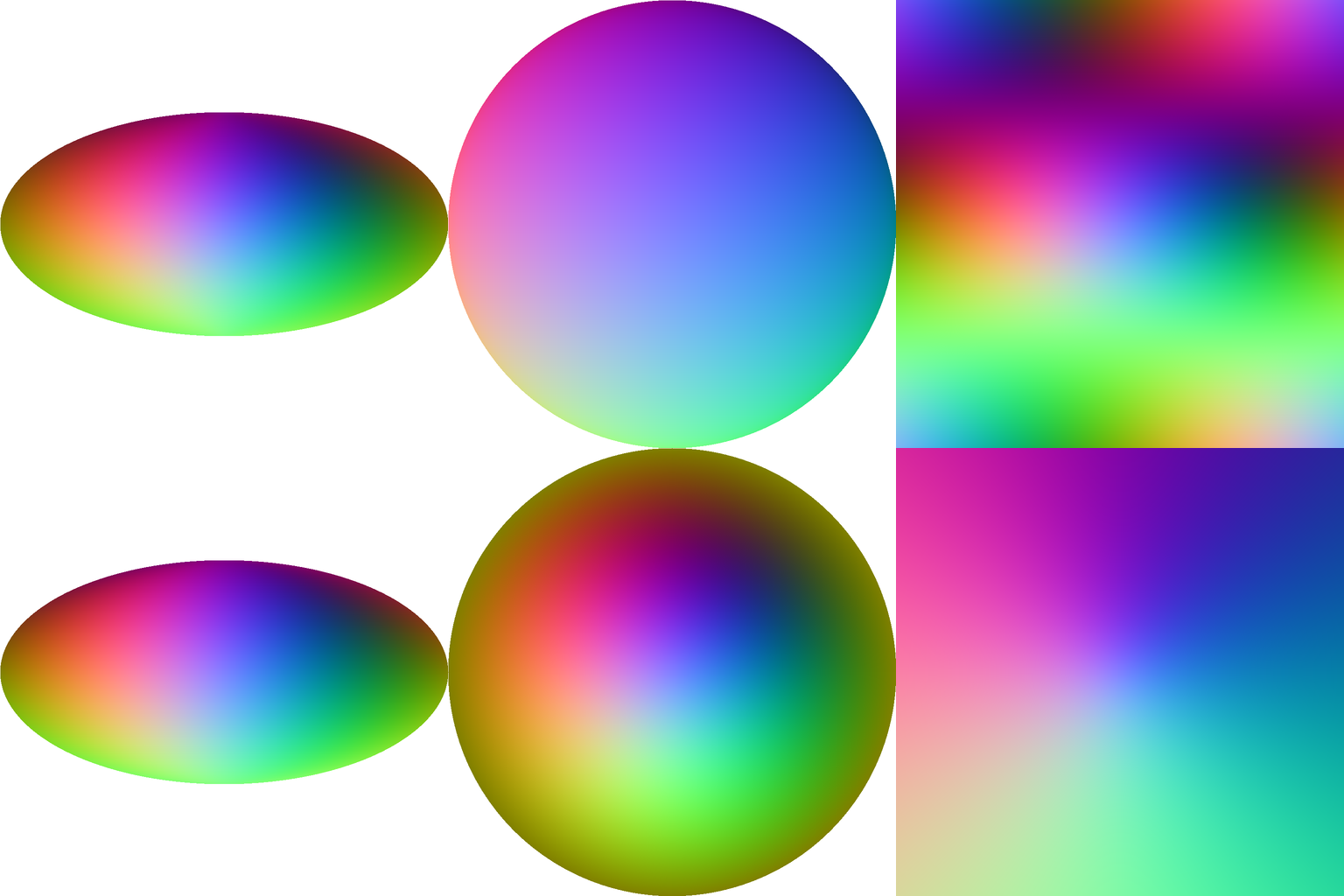
A better approach would be to precompute the unprojection of each fragment! As an example, a texture can store for each 2D pixel a RGB color representing what are the 3D coordinates corresponding to that pixel.
Here are some position textures computed for different allsky projections. Take a pixel, its RGB color corresponds to the XYZ coordinates of the vertex located on the sphere.
The Algorithm Found in the Fragment Shader
From the 2D screen space pixel $p_{ss} \in [-1, 1]^{2}$:
- Map $p_{ss}$ to $[0, 1]^{2}$. $p_{ss} = 0.5 \times p_{ss} + 0.5$
- Perform the unprojection by retrieving the pixel color from the position texture: $p_{ws} = \mathcal{f}_{proj}^{-1}(p_{ss})$. $p_{ws}$ lies on the sphere. Its coordinates are expressed in **world space**.
- Apply a rotation to that point: $p_{ws} = R \times p_{ws}$, where $R$ is the rotation matrix of the sphere.
- Retrieve the HEALPix cell where the vertex is located: $H_{idx}, d_x, d_y = xyz2pix(p_{ws})$ where $d_x, d_y \in [0, 1]$ and $H_{idx} \in (0, 1, …, 11)$. $d_x$ and $d_y$ refer to the location offset within the HEALPix cell index $H_{idx}$ containing $p_{ws}$.
- Retrieve the color of $p_{ws}$
I created an image with the 12 base HEALPix tile images (e.g. at level 0) of the DSS sky survey. The 12 tiles are concatenated together horizontally. Download it to see it in fullsize.

The $uv$ position of $p_{ws}$ within that texture is therefore: $uv = (\frac{H_{idx} + d_x}{12}, d_y)^T \in [0, 1]^2$
Here is the full code of the fragment shader in GLSL:
#version 300 es

// The position in the projected clipping space (2D coords) coming from the VS
in vec2 p_ss;
// The output color of the fragment
out vec4 color;

uniform sampler2D pos_tex; // The texture storing the XYZ positions for every screen pixels
uniform sampler2D tiles_tex; // Image tiles of the 12 base HEALPix cells concatenated

uniform mat4 R; // The rotation matrix of the sphere

vec4 get_color(vec3 pos_ws) {
    // 4.
    // hash_with_dxdy omitted. This returns the HEALPix cell containing
    // pos_ws. You can inspect the code in https://github.com/bmatthieu3/wgpu-sky-rendering
    // for more details.
    HashDxDy hdxdy = hash_with_dxdy(0, pos_ws);
    float idx = float(hdxdy.idx);
    // remap dx and dy computed from hash_with_dxdy
    vec2 d = vec2(hdxdy.dy, hdxdy.dx);

    // 5.
    vec2 uv = vec2((idx + d.x)/12.0, d.y);
    return texture(tiles_tex, uv);
}

void main() {
    // 1.
    // Transform the clip space position from [-1, 1] to [0, 1.0]
    vec2 uv = pos_ss * 0.5 + 0.5;
    // 2.
    // Perform the unprojection by sampling the texture.
    // We get a world space position
    vec3 pos_ws = texture(pos_tex, uv).rgb;

    // 3.
    // Apply to it the rotation matrix of the sphere.
    vec3 pos_ws = vec3(R * vec4(pos_ws, 1.0));

    // 4. and 5. inside get_color
    color = get_color(frag_pos);
}
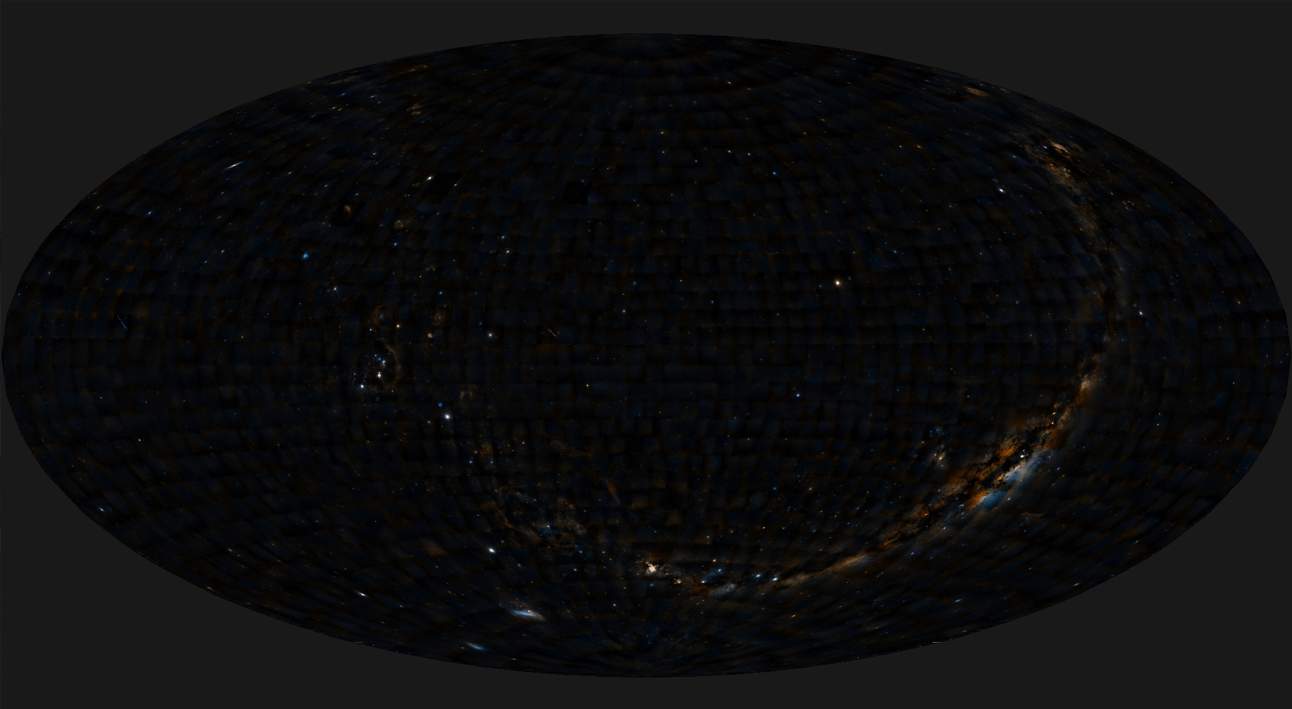
And the result:
Test it
WebGPU implementation
All the source code using wpgu-rs can be found on my github. To test it:
# Clone the repo
$ git clone https://github.com/bmatthieu3/wgpu-sky-rendering.git
$ cd wgpu-sky-rendering

# Compile
$ cargo build --release

# Run
$ cargo run --release
Aladin Lite
There is also a WebGL2 implementation of this rendering process included into the Aladin Lite rendering engine. It can be tested (with the WebGL2 experimental feature enabled on your browser) here.
This version does not do the unprojection for every pixel so it has some distortion effects on the border of the projections. This has been fixed in the current code.
Questions ?
If you have questions or remarks on how to improve the algorithm please email me: baumannmatthieu0@gmail.com.
You can also push an issue and contribute on the wgpu-sky-renderer or aladin-lite repositories.